Spanning Tree Protocol (STP) is a critical component in network design, particularly in environments utilizing Catalyst switches. STP prevents network loops and ensures a loop-free topology, which is crucial for maintaining a stable and efficient network. This article delves into the fundamentals of STP, its importance, and a step-by-step guide on configuring STP on Catalyst switches.
What is the Spanning Tree Protocol (STP)?
Spanning Tree Protocol (STP) is a network protocol that ensures a loop-free topology for Ethernet networks. STP was developed to prevent bridge loops and the broadcast radiation that results from them. It works by identifying redundant paths in a network and selectively blocking some paths while leaving others open, thus ensuring there is only one active path between any two network devices.
Importance of STP
- Prevents Network Loops: Without STP, redundant links in a network can create loops, leading to broadcast storms, multiple frame copies, and MAC table instability.
- Improves Network Stability: By managing redundant paths, STP helps maintain network stability and ensures consistent communication paths.
- Enhances Redundancy: STP allows for redundant links that can be activated if the primary path fails, thus providing fault tolerance and high availability.
How STP Works
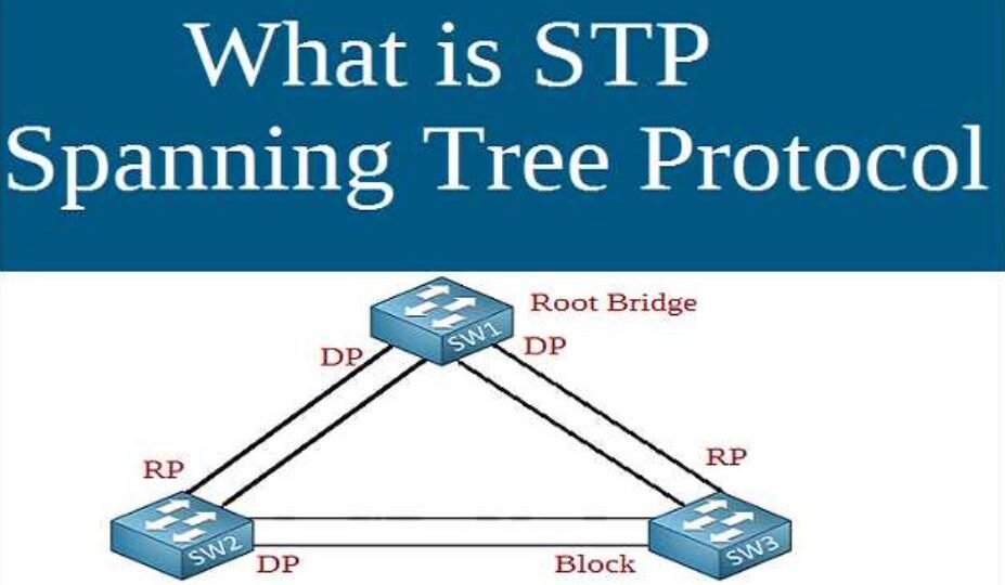
STP operates by electing a root bridge, which is the central reference point in the network. All other bridges (switches) determine the shortest path to the root bridge and disable any redundant paths that could cause loops. The process involves:
- Bridge Protocol Data Units (BPDUs): Switches exchange BPDUs to share information about their ports and connections.
- Root Bridge Election: The switch with the lowest bridge ID (priority and MAC address) is elected as the root bridge.
- Path Cost Calculation: Each switch calculates the path cost to the root bridge and identifies the root port (the port with the lowest cost to the root).
- Designated Port Selection: For each network segment, the switch with the lowest path cost to the root bridge becomes the designated bridge, and its port is designated as the designated port for that segment.
- Blocking Redundant Paths: Any ports that do not serve as root ports or designated ports are put into a blocking state to prevent loops.
Configuring STP on Catalyst Switches
Configuring STP on Catalyst switches involves several steps, including selecting the STP mode, setting priority values, and verifying the configuration. Here’s a detailed guide:
Step 1: Select STP Mode
Catalyst switches support multiple STP modes, including:
- Classic STP (IEEE 802.1D): The original version, which can be slower in convergence.
- Rapid STP (RSTP, IEEE 802.1w): An improvement over classic STP, offering faster convergence.
- Multiple STP (MSTP, IEEE 802.1s): Supports multiple spanning trees for different VLANs.
To configure the STP mode, use the following commands:
bash
Copy code
switch(config)# spanning-tree mode {stp | rapid-pvst | mst}
For instance, to enable Rapid PVST+ (a Cisco enhancement to RSTP):
bash
Copy code
switch(config)# spanning-tree mode rapid-pvst
Step 2: Set Bridge Priority
The root bridge is selected based on the lowest bridge ID, which comprises a priority value and the switch’s MAC address. You can influence which switch becomes the root bridge by setting a lower priority value.
bash
Copy code
switch(config)# spanning-tree vlan <vlan-id> priority <value>
For example, to set the priority for VLAN 10 to 4096:
bash
Copy code
switch(config)# spanning-tree vlan 10 priority 4096
Step 3: Configure PortFast and BPDU Guard
PortFast is a Cisco feature that allows ports connected to end devices (like PCs) to skip the listening and learning states, transitioning directly to the forwarding state. This reduces the time it takes for devices to connect to the network.
bash
Copy code
switch(config-if)# spanning-tree portfast
To enable BPDU Guard on PortFast-enabled ports to protect against accidental loops:
bash
Copy code
switch(config-if)# spanning-tree bpduguard enable
Step 4: Verify STP Configuration
After configuring STP, it’s essential to verify the configuration and ensure everything is functioning correctly.
- Show Spanning Tree Status: Displays the STP status for all VLANs.
bash
Copy code
switch# show spanning-tree
- Show Spanning Tree for Specific VLAN: Provides detailed information about STP for a particular VLAN.
bash
Copy code
switch# show spanning-tree vlan <vlan-id>
- Show Spanning Tree Summary: Summarizes the STP configuration for quick overview.
bash
Copy code
switch# show spanning-tree summary
Example Configuration
Here’s an example configuration for enabling Rapid PVST+, setting the priority for VLAN 10, and configuring PortFast and BPDU Guard:
bash
Copy code
switch(config)# spanning-tree mode rapid-pvst
switch(config)# spanning-tree vlan 10 priority 4096
switch(config)# interface range gigabitethernet 1/0/1 – 24
switch(config-if-range)# spanning-tree portfast
switch(config-if-range)# spanning-tree bpduguard enable
Troubleshooting STP Issues
Despite careful configuration, STP issues can arise. Here are some common troubleshooting steps:
- Check for Incorrect Port States: Verify that ports are in the expected STP state (e.g., forwarding, blocking).
bash
Copy code
switch# show spanning-tree interface <interface-id>
- Verify Root Bridge Election: Ensure the intended switch is the root bridge.
bash
Copy code
switch# show spanning-tree root
- Inspect BPDU Reception: Confirm BPDUs are being received and processed correctly.
bash
Copy code
switch# debug spanning-tree bpdu receive
Conclusion
Understanding and configuring STP on Catalyst switches is essential for maintaining a stable and efficient network. By following the steps outlined in this guide, you can effectively manage and optimize your network’s spanning tree configuration. Properly configured STP not only prevents network loops but also enhances network redundancy and reliability, ensuring seamless connectivity and performance.
For More Articles Click
RELATED POSTS
View all

Mastering Digital Domination: Unleash Your Potential with a Digital Marketing Course in Malaysia
June 13, 2024 | by Mohamed Azik


Global HVAC Pump Market Share, Size, Trends, Growth, Report and Forecast 2024-2030
July 4, 2024 | by Smith7